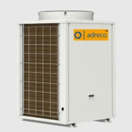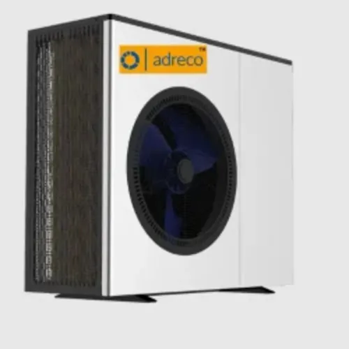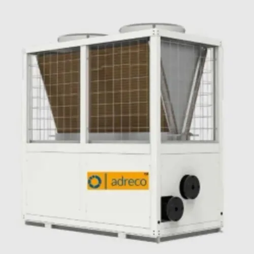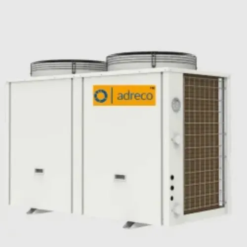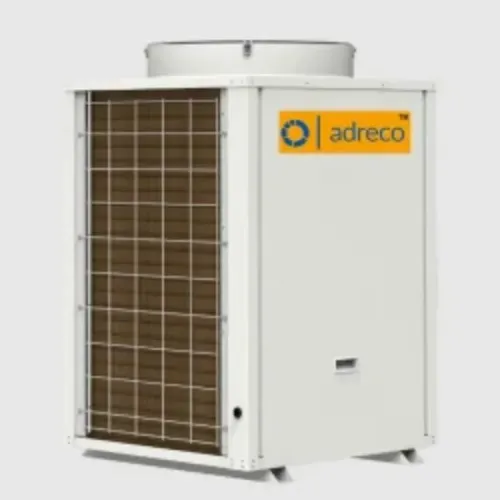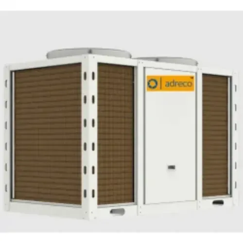
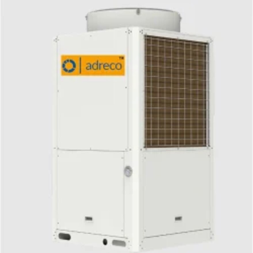
As outdoor air cools, an air-source heat pump must extract heat at a lower evaporation pressure while still delivering water at the required temperature. You will learn how vapour injection limits that performance loss, how to interpret cold-weather test data, and which installation details determine whether the system meets your building’s design load.
Key takeaways
- EVI raises low-temperature heating capacity by injecting intermediate-pressure refrigerant vapour.
- Read output, flow temperature, and COP at your design outdoor temperature.
- Check defrost controls, airflow, pipework, and emitters before comparing compressors.
- Judge seasonal heat delivery across the complete system, not compressor output alone.
Why conventional heat pumps lose output as outdoor air cools
Cold outdoor air gives a standard air-source heat pump less usable heat and forces it to work across a larger pressure lift. As the low ambient temperature falls, the refrigerant evaporates at a lower temperature and evaporation pressure.
Its vapour enters the compressor at lower density, so refrigerant mass flow usually falls; less refrigerant circulating means less heat can be collected and delivered indoors.
At the same time, the heating circuit still demands a condensing pressure set largely by its water temperature. Supplying 50–55 °C water therefore creates a tougher cold-weather condition than supplying 30–35 °C water. The compressor must raise refrigerant from lower evaporation pressure to that condensing pressure, increasing pressure ratio and compression work.
Eventually, the compressor reaches its allowable operating envelope, and controls reduce output or stop the unit.
Capacity and COP fall together for different parts of the same problem. Capacity drops because the system absorbs and moves less heat; COP drops because electrical input per unit of delivered heat rises as compression work increases. Defrost interruptions add another loss when frost blocks the outdoor coil.
Enhanced Vapour Injection can preserve more refrigerant flow and extend low-temperature operation, but it cannot remove the thermodynamic penalty of extracting heat from colder air.
How economised vapour injection adds refrigerant flow
An economiser creates a controlled intermediate-pressure stage between the condenser and evaporator. This is the basis of economised vapour injection, also called Enhanced Vapour Injection (EVI): part of the liquid refrigerant becomes vapour and enters the compressor through its intermediate-pressure injection port, increasing the refrigerant mass flow the compressor handles in cold weather.
The operating sequence is:
- The outdoor coil absorbs heat from cold air, boiling refrigerant at low pressure. The compressor draws in this suction vapour.
- High-pressure liquid leaving the condenser passes through an electronically controlled expansion valve, which reduces its pressure to the intermediate-pressure stage.
- In a flash-tank circuit, that pressure drop separates vapour from liquid. The vapour travels through the injection circuit to the compressor, while the remaining liquid expands again towards the evaporator.
- In a subcooler arrangement, the intermediate-pressure stream removes heat from the liquid line, then the resulting vapour is injected and the subcooled liquid continues to the main expansion device.
- The compressor combines suction vapour with injected vapour before raising both to discharge pressure. The condenser then transfers that heat to the building water circuit.
The electronically controlled valves adjust injection flow and intermediate pressure as outdoor temperature and leaving-water temperature change. Too little injection leaves capacity and discharge-temperature limits in control; too much raises power use and risks poor liquid management. EVI adds heating capacity, but the compressor still pays for compressing the injected vapour.
What the performance table should tell you at design temperature
Match the unit’s heating capacity at your design outdoor temperature and required leaving-water temperature against the building’s calculated heat loss at that same condition. A rating at 7 °C does not prove adequate output at −10 °C or −20 °C.
Ask for a complete-unit performance table, not a seasonal efficiency label. Check these items:
- Design outdoor temperature: Use the cold-weather temperature selected for your site.
- Leaving-water temperature: Match the table value to the water temperature your emitters require.
- Entering-water temperature: Confirm the return-water condition used for the test.
- Heating capacity: Compare this output with the building heat loss in kilowatts.
- COP: Use it to estimate electrical demand; it does not replace the capacity check.
- Electrical input: Confirm whether the figure includes fans, pumps and controls.
A unit rated for operation at −20 °C can still deliver substantially less heat there than at 7 °C. EVI reduces that decline but does not remove it, and it does not guarantee a fixed percentage improvement.
Water temperature changes the result sharply. Supplying 50–55 °C water creates a harder operating condition than supplying 30–35 °C water, with lower COP and potentially lower capacity. Check domestic hot-water data separately: cylinder charging at roughly 50–60 °C can require backup heat even when low-temperature space heating meets demand.
How defrost and installation conditions protect delivered heat
Frost acts like an insulating blanket on the outdoor coil and blocks the outdoor-coil airflow. The controller starts a defrost cycle from coil-temperature and operating-time data; during reverse-cycle defrost, hot refrigerant warms the coil and the heat pump delivers little or no useful space heat.
Poor tuning causes unnecessary cycles, while delayed defrost chokes airflow and cuts output.
Protect performance by checking these details before winter:
- Keep the coil clear of leaves, snow, fencing and stored materials; follow the manufacturer’s clearance around the fan inlet and outlet.
- Provide unobstructed drainage beneath the coil. Meltwater that refreezes in the base pan can block airflow and damage the fan, so use the specified drain arrangement and pan heater where required.
- Maintain design water flow through the heat exchanger. Clean strainers, an adequately sized pump, open valves and correctly set flow protection prevent low-flow trips and poor heat transfer.
- Insulate heating-water pipes, valves and fittings continuously, with sealed vapour-resistant joints. Uninsulated pipework sheds heat before water reaches the building.
- Clean the outdoor coil and inspect sensors, fans, drain paths and electrical connections before the heating season.
Check the installation against this failure pattern:
| Condition | Protection | Loss if neglected |
|---|---|---|
| Clear coil and fan path | Required clearance and cleaning | Lower capacity and longer defrost |
| Free-draining base pan | Drain outlet and frost control | Ice buildup and fan damage |
| Stable water flow | Pump, valves and clean strainer | Trips or inadequate heat transfer |
| Continuous insulation | Sealed pipe insulation | Heat lost outdoors |
| Accurate defrost sensors | Functional coil sensor and controls | Excess cycles or restricted airflow |
How to judge the complete heating system, not just the compressor
Judge EVI as part of the heat-delivery system: confirm its maximum flow temperature, minimum water volume, controls and measured output at your design conditions.
- Match the maximum flow temperature to the emitter. A unit producing useful output at 35°C for underfloor heating may deliver less capacity or need backup heat while charging domestic hot water at 50–60°C.
- Check the minimum water volume against the installation. Small zones, thermostatic valves and frequent compressor cycling can leave too little water in the circuit; a correctly sized buffer tank provides stable flow and protects control performance.
- Specify backup heat for peak building loss, extreme cold, defrost recovery or high-temperature hot water. Bivalent controls must define when a resistance heater, boiler or other source starts; its presence does not prove that EVI has failed.
| System check | Evidence to request | Failure revealed |
|---|---|---|
| Space heating | Capacity and COP at outdoor design temperature and entering/leaving water temperatures | Insufficient output in cold weather |
| Hot-water cylinder | Capacity at 50–60°C leaving water temperature | Slow recovery or frequent backup heat |
| Whole installation | Minimum water volume, buffer arrangement and pump flow limits | Cycling, flow alarms or unstable operation |
| Supplier claim | Test standard, refrigerant, auxiliary-power accounting and defrost conditions | Marketing figures that cannot predict delivered heat |
Ask Adreco Engineering Pvt Ltd for complete-unit data, not a generic EVI percentage, and verify whether electrical input includes pumps and fans. Seasonal efficiency cannot replace a guaranteed capacity at your cold-weather design point.
Related products
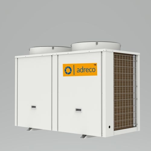 | EVI Heat Pump ₹195000 features: 1. Operating ambient temperature range up to -30° C to 43° C. 2. Hot water temperature upto 60° C. 3. View product → |
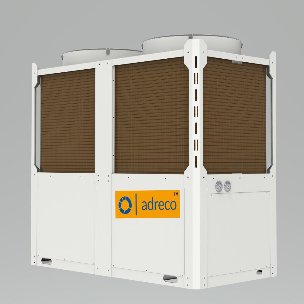 | Heat Pump Central Heating System Heat Pump Central Heating System ₹200000 Features: 1. Operating ambient temperature range up to -30° C to 43° C. 2. Hot water temperature upto 60° C. 3. View product → |
Frequently asked questions
Why does a conventional heat pump lose output as outdoor air cools?
Colder air lowers the refrigerant’s evaporation temperature and pressure while increasing the pressure lift to the heating circuit. That reduces heating capacity and efficiency.
How does economised vapour injection improve low-temperature performance?
An economised vapour injection circuit adds refrigerant at an intermediate pressure during compression. The extra mass flow increases heating capacity and helps control compressor discharge temperature.
What should a heat-pump performance table show at design temperature?
Check heating capacity, electrical input, COP, leaving-water temperature, airflow conditions, and defrost status at the outdoor temperature used for system design.
How do defrost and installation conditions affect delivered heat?
Defrost temporarily diverts energy from heating, while blocked airflow, incorrect water flow, poor pipe insulation, and unsuitable emitters reduce heat delivered indoors.
How should you compare a complete heating system rather than only its compressor?
Compare seasonal heat delivery, controls, emitters, circulation pumps, backup heating, defrost behaviour, installation quality, and performance at the building’s design temperature.