A large building can have a warm thermostat, cold perimeter rooms, overheated ceilings and slow-to-heat floors at the same time. By matching heat loss, water flow, emitters and controls to each zone, you can identify why temperatures vary and set up a system that delivers steadier comfort.
Key takeaways
- Balance each pipe circuit against the room’s calculated heat loss.
- Check airflow, insulation and emitter placement before increasing boiler or heat-pump output.
- Use weather compensation and room sensors to reduce temperature swings.
- Test warm-up time and temperature differences before approving the final design.
How heat moves from one heat source to many rooms
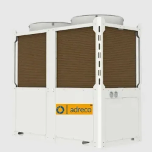
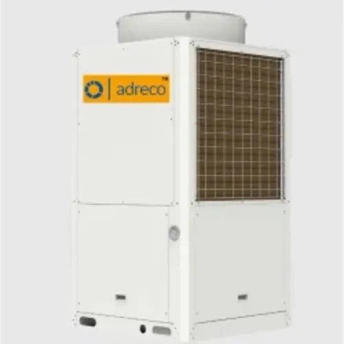
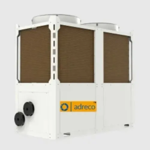
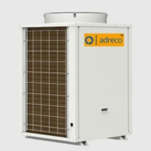
A central heating system distributes heat evenly by moving heated water through separate pipe circuits sized for each room’s calculated heat loss. An air-source heat pump raises the water temperature, while a buffer tank adds thermal volume when the system needs steadier operation; it cannot correct poor sizing or unbalanced circuits.
A heating pump, also called a circulation pump, sends water to headers that divide the flow among controlled circuits:
- Radiator circuits deliver heat through wall-mounted emitters.
- Fan-coil circuits use a fan to transfer heat quickly into larger rooms.
- Underfloor loops spread low-temperature heat across broad floor areas.
Each circuit needs the specified flow rate, suitable pipe length and enough pump head. Long, uninsulated runs lose heat and create pressure differences, so remote rooms can stay cold while the heat source and nearby emitters feel hot. Insulate pipework outside conditioned areas and balance the circuits during commissioning.
Zone valves or manifold actuators regulate delivery according to local thermostats, rather than relying on one centrally located sensor. A thermostat that satisfies its own room cannot detect a cold perimeter office, hall or bedroom.
Room-by-room heat-loss calculations, including windows, ventilation, ceiling height and outdoor design temperature, determine the required emitter capacity before the distribution system is installed.
Why one large space develops hot and cold areas
A single thermostat cannot represent temperatures across a large building. It may turn the heating off after its own area reaches 21°C while a distant perimeter room remains cold, because each space has a different heat loss, occupancy pattern and exposure.
Uneven temperatures usually come from these conditions:
- Solar gain warms rooms with large, sun-facing windows, reducing their heating demand while shaded rooms still need heat.
- High ceilings create temperature stratification: warm air collects above the occupied zone, leaving the floor-level area uncomfortable.
- Perimeter rooms lose more heat through external walls, windows and roofs than rooms surrounded by conditioned spaces.
- Draughts and open doors move warm air into corridors or adjacent rooms, while outdoor air entering through gaps increases the load near entrances.
Zoning corrects the imbalance by dividing the building into areas with similar schedules and heat loads. Each zone needs a separate pipe circuit or underfloor loop group, a control valve or actuator, and a sensor placed away from doors, radiators and direct sunlight.
Adding thermostats without separating the hydraulic circuits does not create independent control; one zone can still receive heat whenever another calls for it.
Set offices, halls, production areas and bedrooms as separate zones when their use or exposure differs. Size each zone from its own heat-loss calculation rather than a whole-building floor-area average, then control it to its actual demand. A buffer tank can reduce short cycling, but it cannot cure poor zoning or an incorrectly balanced system.
How design temperature and water flow determine emitter output
Every zone receives enough heat only when its emitter can replace the zone’s calculated heat loss at the available water flow. A room-by-room heat-loss calculation uses the local design outdoor temperature and intended indoor temperature. It also accounts for fabric U-values, window area, ventilation, ceiling height and adjacent spaces.
Floor area alone misses perimeter rooms and high-loss entrances.
Emitter size must match the water temperature available. Radiator output is commonly quoted at ΔT50, a 50 K mean-water-to-room difference. A heat pump supplying 35–45°C water produces substantially less output from the same radiator than a hotter boiler system, so increase radiator area or add capacity when required.
- Radiators: place them near cold windows or external walls to counter downdraughts; undersized units leave the perimeter cold.
- Fan-coil units: use their rated airflow and water temperature; blocked filters or low fan speed reduce delivered heat.
- Underfloor loops: size loop length and spacing for the design load; excessive length restricts flow, while high thermal mass makes rapid recovery slow.
Hydraulic balancing then assigns each circuit its design flow. Adjust radiator lockshield valves, manifold flow meters or commissioning valves so nearby circuits cannot take excess water from remote ones. A correctly sized heat pump still leaves distant rooms cold if pipe resistance, pump head or valve settings prevent their required flow.
How sensors and weather compensation keep temperatures steady
Put each sensor where the people and equipment in that zone experience the average conditions: about 1.2–1.5 metres above the floor, on an internal wall, with free air circulation. Room thermostat placement fails when the sensor sits beside a heat source or receives an artificial heat stream.
- Keep it away from external doors, radiators, direct sunlight and supply-air outlets.
- Use a separate sensor for each zone with a different schedule or heat load.
- Do not use one central sensor to control a large building; it can stop heating while distant rooms remain cold.
Calibrate each sensor against a checked thermometer placed beside it at the occupied height. Let both readings stabilise before applying the controller’s measured offset, then verify the reading after the heating has operated through a normal cycle. Record the sensor location and calibration offset during commissioning.
Weather compensation changes the heating-water target as outdoor temperature changes. Set the heating curve against the building’s design heat loss and adjust its slope or parallel shift from observed indoor temperatures. A lower flow temperature reduces heat-pump effort, while gradual adjustment prevents the full-on/full-off swings caused by a fixed thermostat.
Check flow and return temperature at stable operation, not immediately after startup. Hydraulic balancing and circuit flow rates matter just as much: restrict over-supplied nearby circuits and confirm remote loops receive their design flow.
If the return temperature is unexpectedly high or a distant circuit remains cool, correct the flow distribution before raising the heat-source temperature.
How to test consistency, warm-up time and the final system choice
Use temperature data loggers to test the building, not one centrally located thermostat. Place them in representative perimeter rooms, interior zones, high-occupancy areas and near the coldest external walls, away from radiators, sunlight and supply-air outlets. Record at short intervals during occupied hours and compare each zone’s readings with its target.
1. Start from a known indoor temperature and record the warm-up time after a setback. Note outdoor temperature, occupancy, door positions and solar exposure, because these change the result.
2. Run the system through a cold period and inspect the logger traces for persistent room-to-room differences, overshoot and repeated cycling. Underfloor heating has high thermal mass, so judge steady operation rather than expecting rapid recovery.
3. During heat-pump commissioning, record flow and return temperatures, every circuit’s flow rate, emitter temperatures, sensor locations and weather-compensation settings. Check operation near the local design outdoor temperature, or use a controlled test that represents the design load.
4. Correct faults before increasing plant size. Balance circuits, relocate misleading sensors and adjust controls; a larger buffer tank cannot fix poor zoning or incorrect hydraulic design.
Choose the system that meets each room’s design heat loss, calculated from fabric U-values, ventilation, windows, ceiling height and adjacent spaces—not floor area alone. When reviewing an Adreco Engineering Pvt Ltd proposal, request these commissioning records and the room-by-room calculation before comparing equipment capacity.
Related product
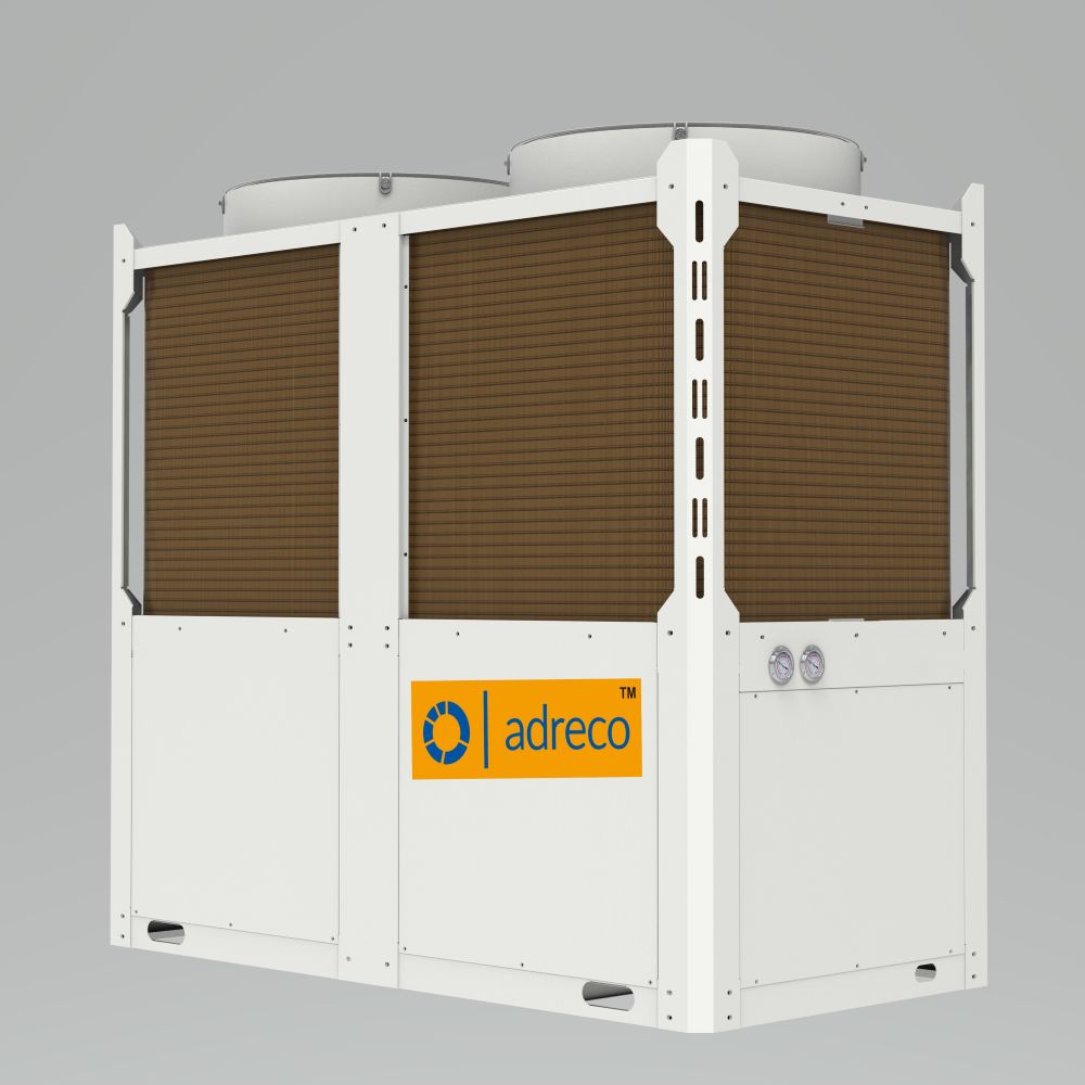 | Heat Pump Central Heating System Heat Pump Central Heating System ₹200000 Features: 1. Operating ambient temperature range up to -30° C to 43° C. 2. Hot water temperature upto 60° C. 3. View product → |
Frequently asked questions
How does central heating deliver heat to multiple rooms?
A heat source warms water, which travels through separate pipe circuits to emitters sized for each room’s heat loss.
Why can one large space have hot and cold areas?
Uneven insulation, air movement, emitter placement, blocked airflow and unbalanced circuits can create temperature differences.
How do water flow and design temperature affect heating output?
Emitter output depends on water temperature, flow rate, emitter size and the room’s design heat loss; poor sizing limits performance.
How do sensors and weather compensation maintain a steady temperature?
Room sensors adjust system operation to indoor conditions, while weather compensation changes water temperature as outdoor conditions change.
How can you test whether a central heating system is consistent?
Measure temperatures at several points, record warm-up time, check circuit flow and compare results with the design targets.